L3VPNv4 over SRv6 BE with FRR
Welcome to the first post in the series about segment routing with IPv6 dataplane (SRv6). Post walks through how unicast connectivity between two IPv4 nodes works within an L3VPN/SRv6 using FRR. Files are available in my git.
My setup:
- AWS EC2 on debian 12 (bookworm) with Linux Kernel Version:
6.1.0-29-cloud-amd64 - containerlab version:
0.62.2 - docker version:
27.5.0 - FRR version:
10.2
A few words about setup
The setup was tested on both Debian 12 and Ubuntu 22.04.
On Ubuntu, the VRF module is missing from the default AWS kernel build. To fix this, run:
1
apt install linux-modules-extra-`uname -r`
Configurations are saved in l3vpnv4srv6be/<device>/frr.conf. Kernel parameters are configured using sysctl and impact the overall operation of FRR.
In Containerlab, each FRR instance starts in an isolated container, where the daemons, frr.conf, and sysctl are configured separately for each container.
Iproute2 is used by default for creating VRF.
How VRF works in Linux
The setup.sh script runs inside each container.
Depending on the device’s role, it may include sysctl settings, VRF configuration, or dummy interface configuration.
The enable-ipv6-forw.sh script enables IPv6 forwarding on all required devices.
Topology
Figure 1 shows the topology where:
- PE1/PE2 use iBGP to advertise prefixes for the L3VPNv4 service prefixes to each other.
- PE1/PE2 use end-to-end SRv6 paths in best-effort mode.
- IS-IS is used between PE1/P/PE2.
- CE1/CE2 use eBGP.
 Figure 1
Deploy topology
To deploy the full topology, run the following commands in the cli:
1
2
clab deploy --topo l3vpnv4srv6be.yaml
./enable-ipv6-forw.sh
To verify the data plane operation between CE1 and CE2, run the following command in the cli:
1
docker exec clab-frrsrv6-ce2 ping -I 2.2.2.2 1.1.1.1
If the ping is successful, it means the connection between CE1 and CE2 is working and we can jump into the details, starting with:
IS-IS and SRv6
Figure 2 shows the topology related to IS-IS and SRv6, where IS-IS is configured on PE1/P/PE2, and SRv6 is configured on PE1/PE2.
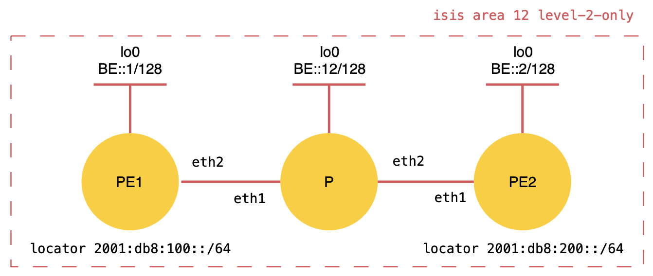 Figure 2
IS-IS uses link-local IPv6 addresses, so for simplicity it’s easier to refer to interfaces by name. PE1 eth2 looks at PE2 eth1 and vice versa.
Example ISIS and SRv6 configuration for PE1:
1
2
3
4
5
6
7
8
9
10
11
12
13
14
15
router isis 12
 is-type level-2-only
 net 49.0012.0000.0000.0001.00
 topology ipv6-unicast
 segment-routing srv6
  locator locator-name "format: `locator <name>` tells isisd to request and use locator from zebra"
  interface sr0 "default option (shown here to clarify; installed in each container during setup.sh)"
!
segment-routing
 srv6
  encapsulation
   source-address be::1 "address in the SA field in the outer IPv6 header"
  locators
   locator locator-name
    prefix 2001:db8:100::/64 "SRv6 SIDs are allocated within this prefix"
In FRR before 10.x, the mechanism called “label chunk” dynamically allocates new SIDs by default using a single shared locator prefix for routing daemons. Communication between the daemon and Zebra is asynchronous and default SRv6 locator owner = ‘system’.
Here is the logic of SID allocation in FRR before 10.x (Figure 3):
- Zebra receives a call from isisd
- Zebra allocates a chunk from the locator and sets isisd as owner
- isisd receives the response with chunk from Zebra
- isisd can allocate a SRv6 SID from chunk
- isisd allocates SRv6 SID and sends request to zebra
- Zebra adds srv6 sid include function to rib
- isisd releases an SRv6 locator chunk
- zebra changes the owner to ‘system’ that other daemons can use SRv6 locator
Only one daemon can use a single locator at a time
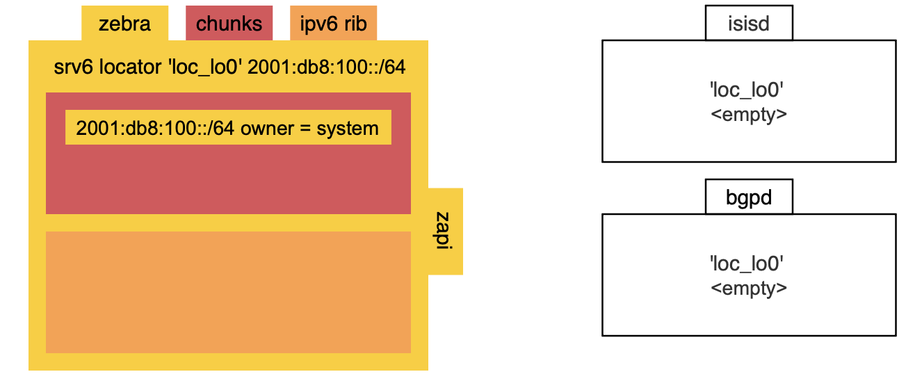
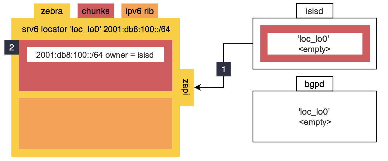
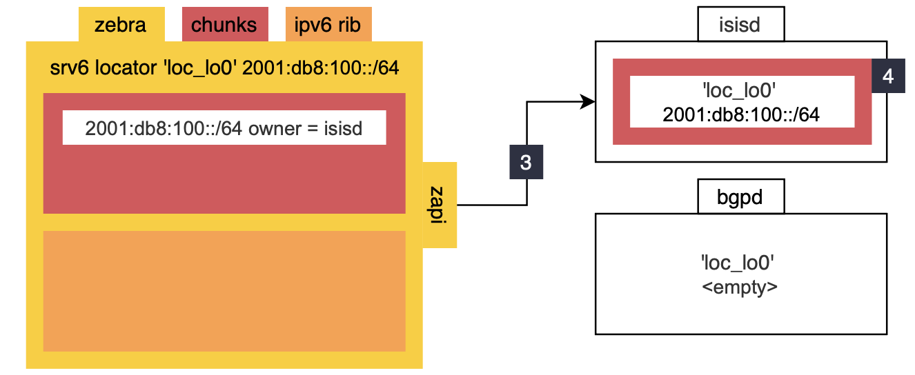
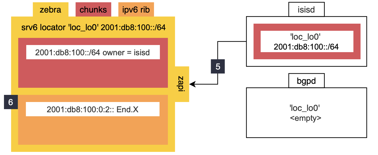
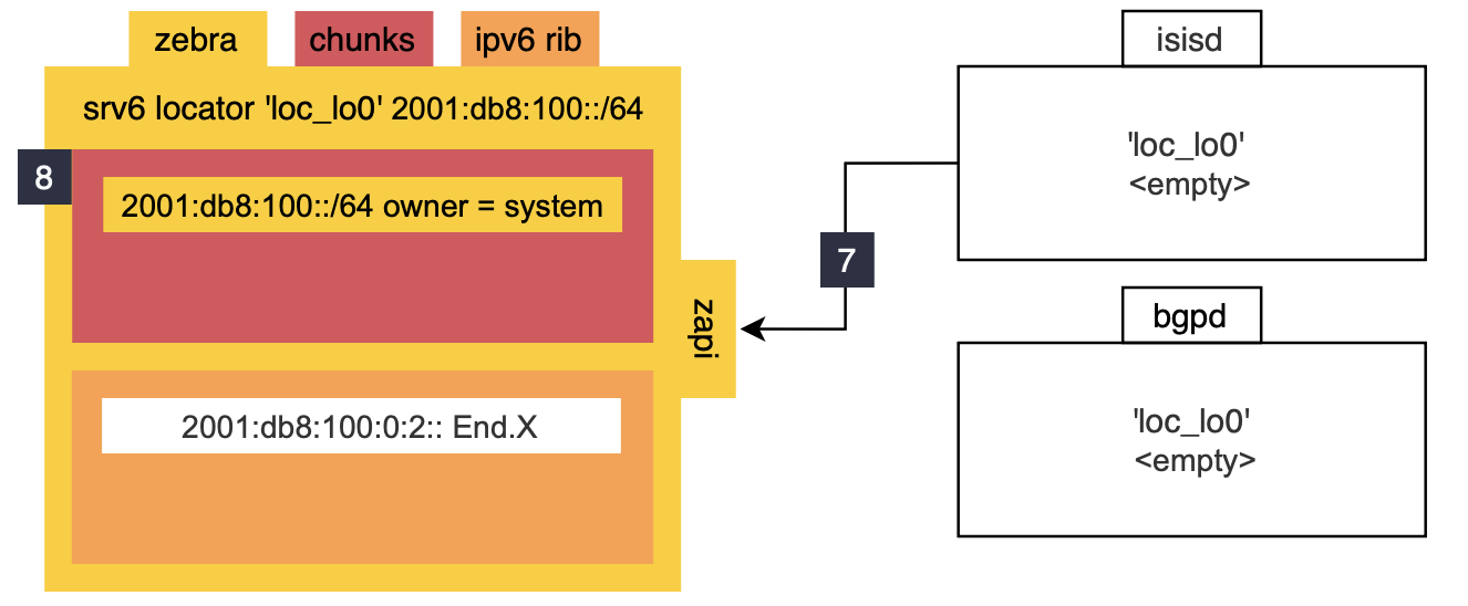 Figure 3 In FRR starting with 10.x, Zebra acts as the central SRv6 SID Manager. This changes the chunk allocation logic and daemons can share the same locator.
Here is the logic of SID allocation in FRR starting with 10.x (Figure 4):
- isisd requests a locator from Zebra
- Zebra assigns a locator
- isisd receives and stores the locator
- isisd sends a SID allocation request to Zebra with context: behavior, next-hop, interface
- Zebra allocates the SID internally: selects the function number, composes the IPv6 address
- Zebra sends an allocation notification back to isisd with the allocated SID address
- isisd sends a route install request to Zebra
- Zebra installs the SRv6 SID into RIB
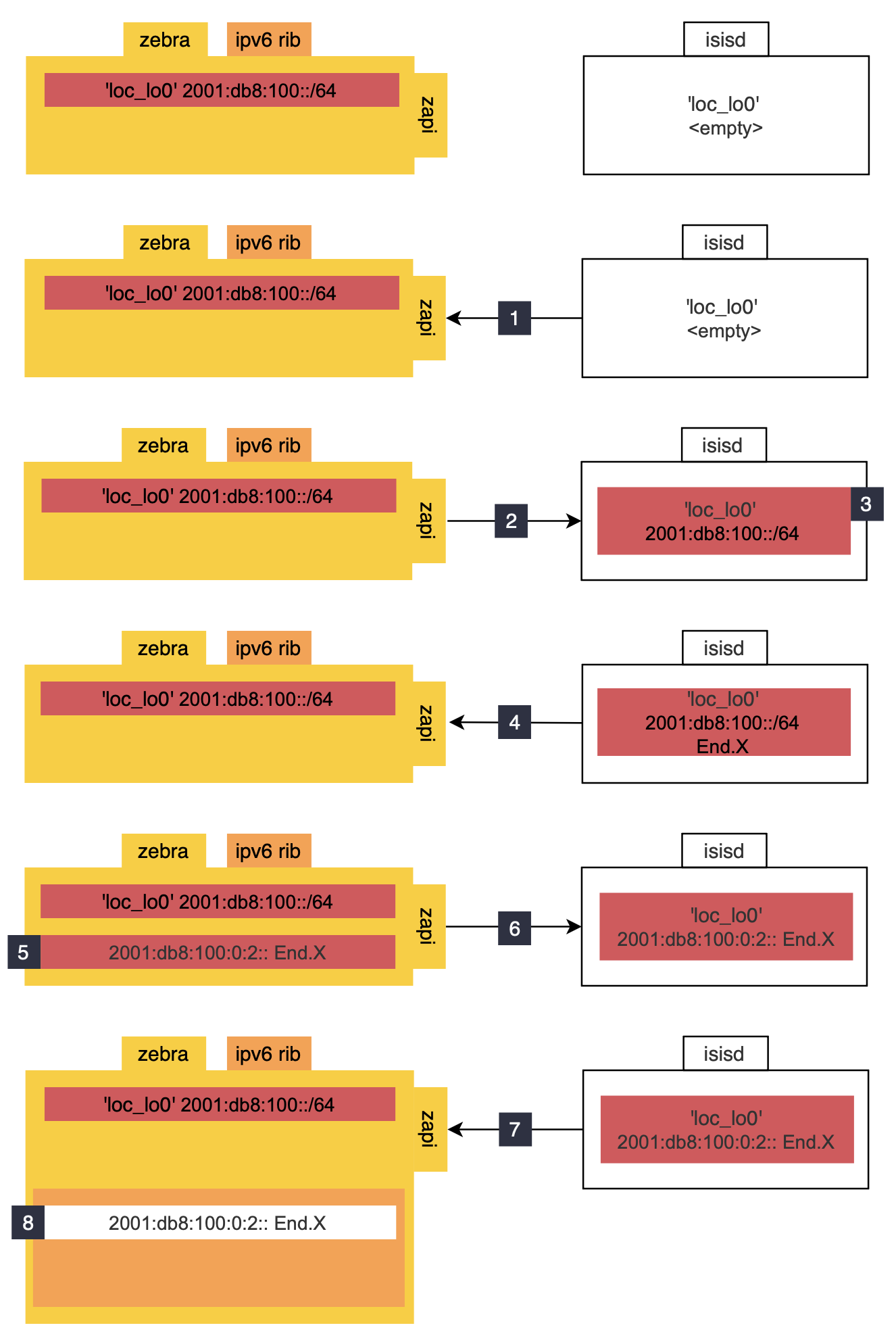 Figure 4
For manual SRv6 SID allocation, Iproute2 is used.
Example of manual End.X SID allocation:
ip -6 route add <ipv6 prefix> encap seg6local action End.X nh6 <next hop> dev <intf>
In FRR, each major protocol is implemented in its own daemon, and these daemons communicate with a middleman daemon (Zebra), which is responsible for coordinating routing decisions and interacting with the Linux dataplane via Netlink.
And as an additional step, Zebra pushes the route entry with SID to the dataplane via Netlink (Figure 5). 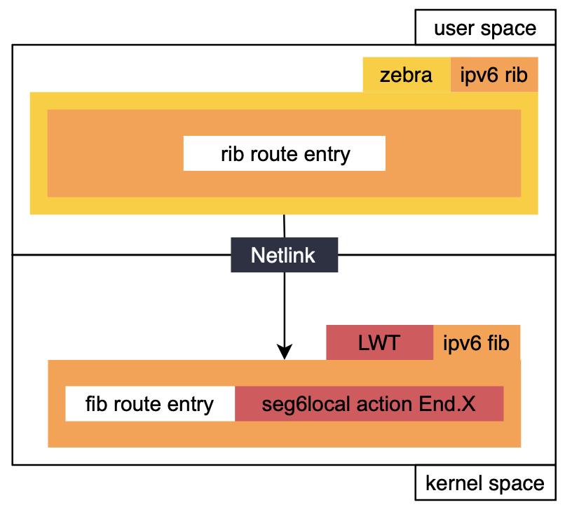 Figure 5
following command in the cli help to check RIB about SIDs are allocated on PE1:
1
2
docker exec -it  clab-frrsrv6-pe1 vtysh
show  ipv6 route
and the result will be:
I>* 2001:db8:100:0:2::/128 [115/0] is directly connected, eth2, seg6local End.X nh6\
following command in the cli help to check FIB about SIDs are allocated on PE1:
1
docker exec -it clab-frrsrv6-pe1 bash ip -6 route show
and the result will be:
2001:db8:100:: nhid 17 encap seg6local action End dev sr0 proto isis
2001:db8:100:0:2:: nhid 26 encap seg6local action End.X nh6 dev eth2 proto isis
Once the PEs have allocated SIDs in their RIB, they can advertise SRv6 information into the IGP domain. IS-IS uses TLVs and sub-TLVs to advertise information (Figure 6).
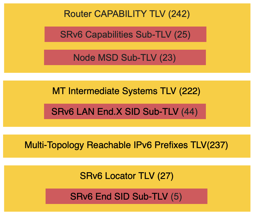 Figure 6
BGP and L3VPN
Figure 7 shows the topology related to BGP and L3VPN. The figure includes an example of the SA/DA encapsulation 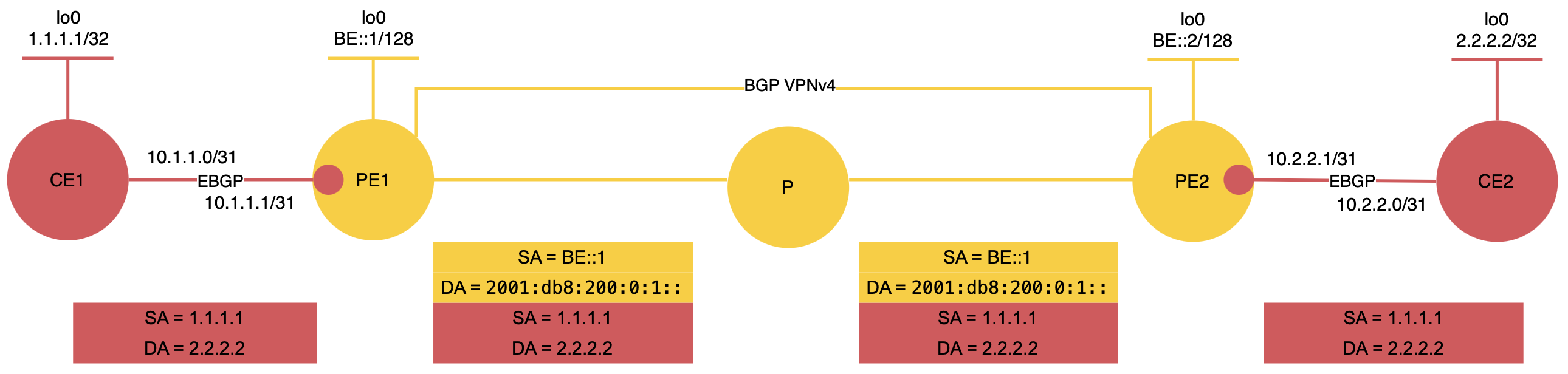 Figure 7 Example BGP and L3VPN configuration for PE1:
1
2
3
4
5
6
7
8
9
10
11
12
13
14
15
16
17
18
19
20
21
22
23
24
25
26
27
28
29
30
31
32
33
34
35
36
37
38
39
40
41
42
43
44
45
46
47
router bgp 12 vrf vrf-ce
 bgp router-id 11.11.11.11
 no bgp default ipv4-unicast
 no bgp network import-check
 neighbor ce-peer peer-group
 neighbor ce-peer remote-as 1
 neighbor 10.1.1.0 peer-group ce-peer
 !
 address-family ipv4 unicast
  neighbor ce-peer activate "enable an address family"
  neighbor ce-peer route-map inbound-bgp-map in
  neighbor ce-peer route-map outbound-bgp-map out
  sid vpn export auto "SID value is automatically assigned"
  rd vpn export 12:1
  rt vpn both 12:1
  export vpn "export of routes between the current unicast VRF and VPN"
  import vpn "import of routes between the current unicast VRF and VPN"
 exit-address-family
exit
!
router bgp 12
 bgp router-id 11.11.11.11
 no bgp default ipv4-unicast
 neighbor PE peer-group
 neighbor PE remote-as internal
 neighbor PE update-source lo
 neighbor PE capability extended-nexthop "allow BGP to install v4 routes with v6 global nexthops"
 neighbor be::2 peer-group PE
 !
 segment-routing srv6
  locator locator-name "format: locator <name>; tells bgpd to request and use locator from zebra"
 exit
 !
 address-family ipv4 unicast
  neighbor PE route-map bgp-vpn-inbound-gl in
 exit-address-family
 !
 address-family ipv4 vpn
  neighbor PE activate "enable an address family"
  neighbor PE next-hop-self
  neighbor PE soft-reconfiguration inbound
 exit-address-family
exit
!
route-map bgp-vpn-inbound-gl permit 10
 set ipv6 next-hop prefer-global "prefer to use the global address as the nexthop"
exit
bgpd allocates the End.DT4 SID in a similar way to isisd, following command in the cli help to check allocated SID on PE1:
1
2
docker exec -it  clab-frrsrv6-pe1 vtysh
show  ipv6 route
and the result will be:
B>* 2001:db8:100:0:1::/128 [20/0] is directly connected, vrf-ce, seg6local End.DT4 table 10
As part of the control plane, PE1 sends PE2 a BGP update that includes a label = 16, the SID value = 2001:db8:100::, and the service data. This means PE2 does not receive the full SID 2001:db8:100:0:1::/128 directly. Instead, PE2 performs transposition to rebuild the full SID, then installs it in its RIB and FIB (Figure 8).
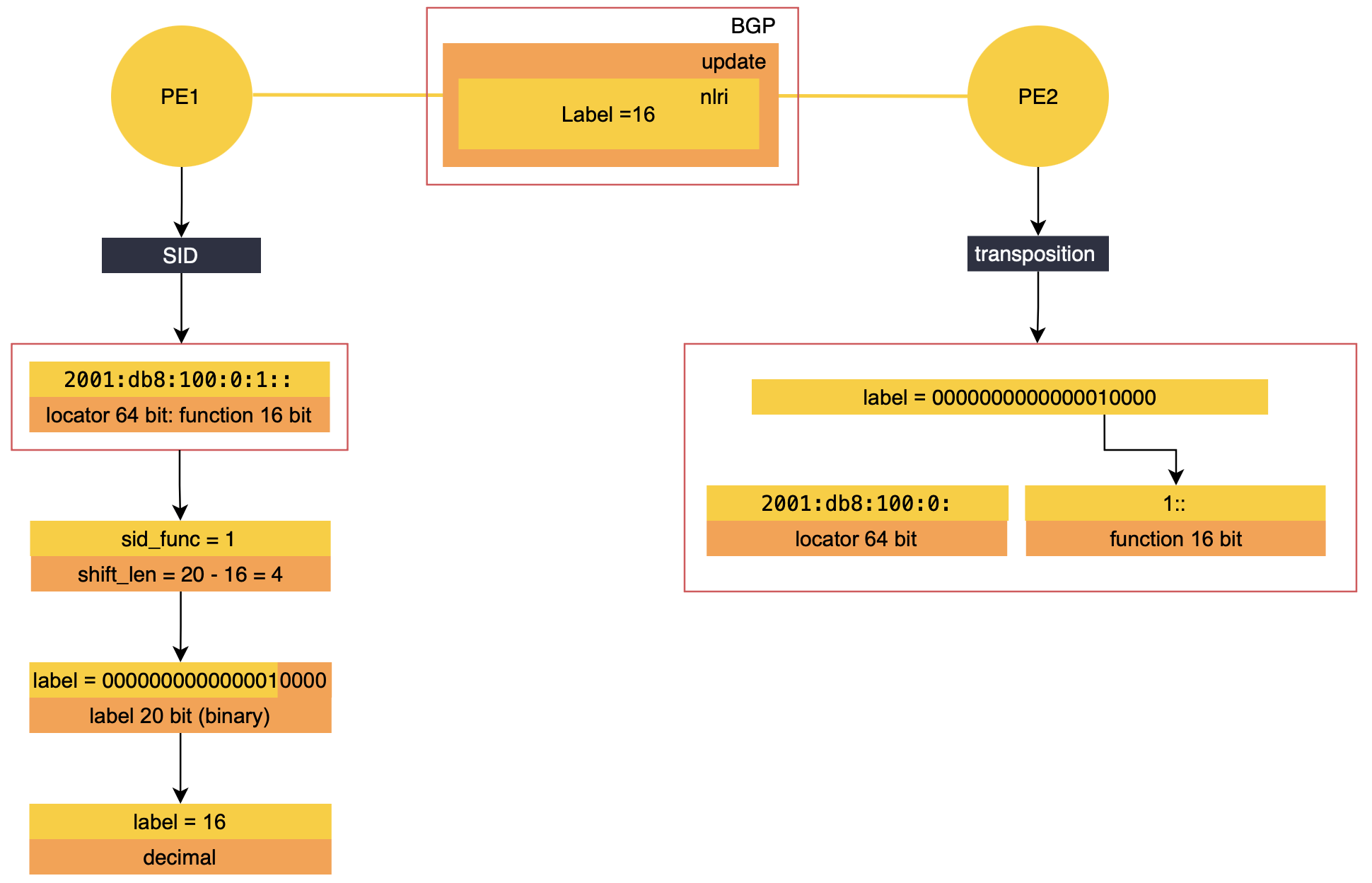 Figure 8
Next-hop reachability on PEs devices is importan in FRR, which is why in
show bgp nexthop detailindirect next hop need to be in valid status.
Finally, these two commands help verify that 2.2.2.2 is installed in the PE1 VRF.
1
2
docker exec -it clab-frrsrv6-pe1 vtysh
show ip route vrf vrf-ce
and the result will be:
B> 2.2.2.2/32 [200/0] via be::2 (vrf default) (recursive), label 16, seg6 2001:db8:200:0:1::, weight 1, 00:01:02
*. via fe80::a8c1:abff:fe3c:ca90, eth2 (vrf default), label 16, seg6 2001:db8:200:0:1::, weight 1, 00:01:02